JMRI implements the CMRInet protocol to send and receive information via changing the state of JMRI objects:
JMRI objects are associated with a single CMRI bit in the case of sensors (input) and lights (output), and one or two bits in the case of turnouts (see the CMRI help page section on setting up turnouts and lights for use with CMRI). With the introduction of microcontroller technology such as the arduino CMRI nodes need no longer be restricted to operate layout hardware based on single (or two) bit commands. Arduinos are quite capable computers that can process CMRINet messages and act on what they receive under local program control. An arduino emulating a CMRI node can be programmed to start animations, play a series of sounds, light buildings in a realistic way, or control the speed of accessory motors -- just about anything the modeller can dream up.
Similarly, it is also possible to send information back to JMRI over CMRINet in the form of numbers or letters, or any string that can be encoded in a few bytes of information. JMRI would receive each byte as setting the state of eight sensors, but a simple JMRI script can translate that binary information into the decimal number or character it represents.
It is also possible to send numbers and characters directly to JMRI from arduinos by using serial communications without taking advantage of JMRI's CMRInet capabilities. Each approach has its advantages and disadvantages, as discussed here.
 One example of this type
of usage would be using two JMRI lights (connected to one CMRI bit apiece) to tell the
arduino to either increase or decrease the speed of a motor attached to an animation
(perhaps a rotating carousel). The arduino can change the speed of the motor and then send
back a number indicating the current speed (perhaps 1 to 8) by encoding that number in
several bits to be sent as part of the CMRINet transmission. A JMRI script can be listening to changes in these "speed"
bits and use them to create a decimal number in a JMRI memory variable for display on a panel, as
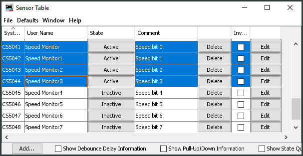
illustrated in a this example script. The image here shows sensors 0, 1, 2, and 3 active which
would translate into the decimal number 15.
One example of this type
of usage would be using two JMRI lights (connected to one CMRI bit apiece) to tell the
arduino to either increase or decrease the speed of a motor attached to an animation
(perhaps a rotating carousel). The arduino can change the speed of the motor and then send
back a number indicating the current speed (perhaps 1 to 8) by encoding that number in
several bits to be sent as part of the CMRINet transmission. A JMRI script can be listening to changes in these "speed"
bits and use them to create a decimal number in a JMRI memory variable for display on a panel, as
illustrated in a this example script. The image here shows sensors 0, 1, 2, and 3 active which
would translate into the decimal number 15.
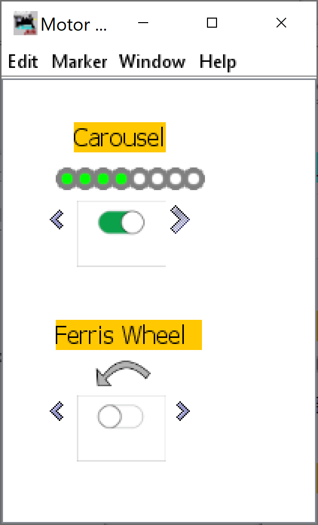 Alternatively, a number of sensor bits can be allocated to a speed display with the arduino
activating the sensors to indicate percentage of maximum speed, as shown in the layout
panel image. Four of the eight bits of this carousel speed control are "lit" or active,
representing a speed of 50% of maximum. The panel also shows the on-off slider control and
clickable greater-than/less-than signs to command the arduino to run the carousel faster or
slower. The bottom part of the panel shows another example with a curved arrow which when
clicked tells the arduino to change the direction of the attached Ferris wheel (currently
off).
Alternatively, a number of sensor bits can be allocated to a speed display with the arduino
activating the sensors to indicate percentage of maximum speed, as shown in the layout
panel image. Four of the eight bits of this carousel speed control are "lit" or active,
representing a speed of 50% of maximum. The panel also shows the on-off slider control and
clickable greater-than/less-than signs to command the arduino to run the carousel faster or
slower. The bottom part of the panel shows another example with a curved arrow which when
clicked tells the arduino to change the direction of the attached Ferris wheel (currently
off).
The steps are fairly straightforward:
Configure a CMRI node representing the number of output bits (JMRI->CMRI node) and input bits (CMRI node->JMRI) desired. Remember that JMRI lights and turnouts output to CMRI and JMRI sensors provide inputs (think of it in terms of the CMRI node: physical sensors input information to the node; the node then outputs information to control physical turnouts and lights).
Create as many JMRI lights as you need to tell the arduino to perform some task. Controlling whether a motor is on or off can be done with a single light (INACTIVE (which sends a 0) for OFF, ACTIVE (which sends a 1) for ON). Controlling its speed requires two lights - one to tell it to increase, one to tell it to decrease, neither on to stay the same speed.
Create sensors as shown above for each byte of information (number or character) you want to receive back from the arduino. If you want to receive the motor speed as a number from zero to seven, you need three sensors. If you want to receive larger numbers, you need more sensors to get more bits. Eight bits can represent numbers up to 255 (the picture here shows bits corresponding to the decimal number 14). Make sure the sensors are linked to the appropriate bits on your arduino/CMRI node.
While JMRI sends and receives a 0 or 1 in the CMRI bit steam, it translates a zero into a sensor INACTIVE state, which is actually stored as 4 (requesting "state" and printing it as a number in a script will return a 4) and ACTIVE as a 2. This is important in writing your JMRI script to translate received sensor states as binary bits.]
Create memory variable to hold each byte of information that will be computed by the script from the eight sensors.
Create a listening script as discussed above to translate the sensor states into bits and create a number of letter in the memory variable. An example script to convert eight sensor states (bits) into a number can be found here.