Each Signal Mast Logic is built from a source and destination Signal Mast pair, along with a series of Blocks, Turnouts and Sensors between the two Signal Masts and the state that they must be in for the source Signal Mast to be released from a "Danger" or "Stop" Aspect.
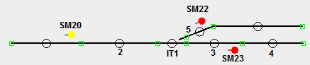
In this first example, you have a source Signal Mast SM20, and two destination Signal
Masts: SM22 and SM23.
The logic behind signaling pair SM20 to SM23 is that Blocks 2 & 3 must be unoccupied, and
Turnout IT1 must be set to "Closed". Once those criteria are met Signal Mast SM20 will be
released from "Danger" to "Caution", if Signal Mast SM23 was set to "Caution" then SM20
would be set to "Proceed" and show a Green Aspect. As soon as Block 2 or 3 becomes Active
or Turnout 1 is set to Thrown, the Signal Mast SM20 is set back to "Danger".
Each Signal Mast pair must be directly reachable from the other, without any other other Signal Mast in-between in the same direction.
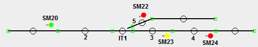
In this second example, a Signal Mast Logic from SM20 to SM24 would be invalid as SM23 is in between the two. You would have to create two separate Signal Mast Logics, one as in example 1 for SM20 to SM23, the second for SM23 to SM24.
Which Aspect our source Signal Mast displays after being released from "Danger" is
firstly determined by the Aspect mapping that has been defined in the Signal Mast
Appearance definition file. If there is only one Aspect that could be displayed, then the
Signal Mast will be set to that Aspect.
However if multiple Aspects could potentially be displayed then the logic looks at two
areas to determine the resulting Aspect to be displayed:
In addition to being able to specify the Turnouts, Blocks and Sensors that make up a Signal Mast Logic, you can also specify which other Signal Masts must be set to a specific Aspect before the source Signal Mast can be released. In general, there should be no need to add extra Signal Masts in the Signal Mast Logic as the route between all the different source mast to destination mast Logis pair should have unique criteria. However there are certain situation such as where two tracks crossover on the same level where a conflicting route could be set. Therefore to get around this, the Signal Mast or Masts that are protecting the crossover should be part of each others criteria.
The Signal Mast Logic window holds two areas showing Block and Turnout information: the first is user generated, the second is where a tool such as used with the Layout Editor (see below) has automatically built up a set of Blocks or Turnouts from the panel layout as signaling criteria.
Both sets of information are used by JMRI to determine if a Signal Mast can be released or not, however the manually created information has a higher priority over the automatically generated information thus allowing the user to over-ride what the system has determined.
The automatically generated information is not saved with the rest of the panel information, but the manually generated user information is. If the Layout Editor is being used to base the Signal Mast Logic on (see below) then JMRI will rediscover this information from the panel each time it is loaded, and if any changes have been saved in the meantime they will be discovered. Please note, that this re-generation of information is not done on the "fly" when a Layout Editor panel is changed and saved without exiting JMRI.
By using the Layout Block Editor, it is possible to have the Signal Mast Logic determine the signaling pairs, along with the Blocks and Turnouts that make up the criteria. This can be done across all the Signal Masts on the Layout Editor or on a source Signal Mast basis.
It has the advantage that if the Layout Editor panel is changed, JMRI will discover this change when the panel is reloaded and use the new Block and Turnout information. Please be aware that the re-discover at load process will not discover any new Signal Logic pairs or remove invalid Signal Logic pairs, it will simply update the information between existing pairs.
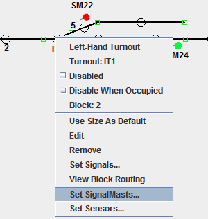
Signal Masts can be placed at Turnouts, anchor points and level crossings, but only where there is a boundary between two different layout blocks.
To add a Signal Mast using a Layout Editor Panel, right click on the Turnout, level crossing or anchor point and if a block boundary exists you will be given the option to "Set Signal Mast..."
You will then be presented with a fresh window that allows you to enter in the name of
the Signal Mast that will protect a boundary between two blocks.
For turnouts and crossings, you can only add a Signal Mast for the boundary going into the
turnout or crossing, it is not possible to add a Signal Mast for the boundary going out
from the turnout or crossing. E.g. if block A is the section of track attached to the
Turnout and the Turnout is in block B, you can only add a Signal Mast that faces into block
A that protects block B; you can not add a Signal Mast that faces into block B to protect
block A.
Using the Panel Editor and not having defined Blocks, the Signal Mast Logic can't be
automatically discovered as this type of Panel only displays individual icons over a layout
graphic so you have to manually add the connections as Blocks using the Blocks Tool or add
Signal Logic Pairs in the Signal Logic Table for every possible connection.
Manually add Signal Icons to your panel by right-clicking and choosing "Add icon".
Signal Mast Logic can automatically be generated in three different ways:
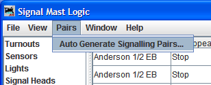 The second method is from the Tools > Auto generate
Signaling Pairs menu in the Signal Mast Logic Table. This will generate Signal
Mast Logic based upon all the Signal Masts on the Layout Editor panel. If not yet active,
it will give you the option to activate Layout Block Routing.
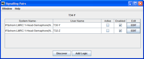
The second method is from the Tools > Auto generate
Signaling Pairs menu in the Signal Mast Logic Table. This will generate Signal
Mast Logic based upon all the Signal Masts on the Layout Editor panel. If not yet active,
it will give you the option to activate Layout Block Routing.You manually add new Signal Mast Logic pairs by clicking either
The Signal Mast Logic works only between a source and destination Signal Mast, so if you have a valid route to an End Bumper/Buffer Stop/Dark Area, then there is no specific destination Signal Mast. In this situation you would create a "dummy" Signal Mast of type Virtual in the Signal Mast Table to act as your destination Signal Mast. It doesn't have to represent a signal on the layout or have Signal Heads associated. All that this Virtual Signal Mast has to do is display a "Danger" aspect.
Back to the Signaling main help page.