This tool provides an automated procedure for assigning signals at Single or double slip.
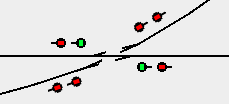
If requested, this tool will place signal icons on the panel at the four entrances, to the slip and will set up control logic for specified signal heads. Either one or two signal heads may be placed at each leg of the slip. The continuing leg is the direct path through the slip from either direction, while the diverging leg is the path that deviates from the direct path.
Prior to selecting this tool, the slip must be on the panel with two turnouts assigned and configured correct for each path, the required signal heads must also be in the Signal Head Table. The control logic created by this tool only works correctly if each of the track segments connected to the slip legs is assigned to a different block. it works best if the track segment assigned to the slip is in a fifth different block, but this is not required.
When this item is selected, a dialog is shown with a combo box to select the slip that is on the current panel and the names (system or user) of six to eight signal heads to be assigned to the two turnouts.
For each signal head, check boxes are available for selecting whether an icon is to be placed on the panel, and whether control logic is to be created for the signal head. Regardless of whether icons are placed or logic is created, Layout Editor will record that the entered signal heads are assigned to the slip.
In the drop down list select the Slip that is located on the panel that you wish to configure, the name populated in the drop down box is made up of the turnout names used to create the slip. On selecting the slip, if signals have already been assigned then this information will automatically be populated.
The tool provides for entry of one or two signals at each leg of the slip, depending upon
the slip type and the leg selected.
These signal heads show the status for moving through the direct or sliped path through the
slip. First the signal heads located at Turnout 1 - continuing track are
entered. The continuing track signal head is required, but the
diverging track entry is optional. If only the continuing
track signal head is entered, the tool assumes that head is signaling both tracks of
the other turnout, similar to when only one signal head is placed at the throat of a single
turnout.
Next the signal heads located at Turnout 1 - diverging track are entered.
Remember this is for when the path through the slip is set to be slipped. When two heads are
entered, the head closest to the slip signals the status of the direct path.
Similarly, the signal heads located at Turnout 2 - continuing track and
Turnout 2 - diverging track are entered.
If there was a signal head previously assigned to any position, and you enter a different signal head in the same place, the new signal head will replace the previous signal head, and the icon of the previous signal head (if there was one) will be deleted from the panel. Similarly, if you replace a previously assigned Diverging signal head with a blank entry (no signal head), the previous entry is deleted, and there will not be any signal head at that position. If a signal head is changed, you must redo any logic that involves it. In particular, if you delete a diverging signal head, you must redo the logic for the continuing signal head located on the same track.
Check Add Signal Icon to Panel to request that an icon for a signal head be placed on the panel at the turnout position indicated.
Check Set up Logic to request that the tool set up signal control logic for a signal head. For each of these signal heads, the tool creates a Simple Signal Logic for that head, and in addition creates a Logix that ensures that the turnout the signal is placed on is not thrown against the leg the signal is placed on. The tool will attempt to setup the logic and automatically fill in entries from the information available. If the tool does not have enough information available to set up the logic, a message results, and you will have to return later after more blocks (with occupancy sensors) and/or signals have been assigned to turnouts and block boundaries on the panel.
The tool will set up the Simple Signal Logic to set all signals red if the slip is occupied. If this is not what you want, you should edit the Simple Signal Logic by removing the occupancy sensor of that block.
When setting up logic, this tool will follow track within a block until it finds a signal at the end of the block away from the turnout being signaled. If your layout contains sections that are signaled and sections that are not, to get this tool to set up logic correctly, you may have to create and assign a virtual signal (a signal that does not correspond to an actual signal on the layout) at the unsignaled end of the block that connects track that is signaled with track that is not signaled. (You do not need to add an icon for the virtual signal to your panel, but it must exist in your signal head table, and must be assigned to a turnout or block boundary using a Set Signals ... tool.) If a block ends with an end bumper, no virtual signal is required at the end bumper end.
If a block has an internal turnout (the turnout, and the track segments at its throat and continuing legs are within the block), the program will expect signals at that turnout even if it's not at the end of the block. However, at times the user may not want to signal a seldom used turnout within a block. When following track through a block, the program will skip over unsignaled internal turnouts if Skip Unsignaled Internal Turnouts is checked in the Layout Editor Tools menu. It will always, however, warn that it is doing so. Use this option with caution. There is no signal protecting against a skipped turnout being set incorrectly, so if an unsignaled internal turnout is not set correctly, derailed trains could result.
When setting up the Logix used in the control logic, the tool creates an internal sensor to communicate with the Simple Signal Logic. The Logix will appear in your Logix table, and the internal sensor will appear in your sensor table. The system names of the Logix and internal sensor will be, IX or IS followed by TTT_HHH, where TTT is the system name of the turnout where the signal head is located and HHH is the system name of the signal head. The purpose of this Logix is to ensure that the aspect of the signal head will be red if the turnout where the signal head is located is switched against the track the signal is on.
This tool sets up three-aspect signaling. When a signal head is showing the status when moving to a diverging route, the tool will set up for limited speed (the least restrictive aspect is not green, but yellow), and the signal will show yellow when it otherwise would show green. You can change this with a simple edit (see below).
If you have a special situation at a signal, you may have to edit the information entered by this tool into the Simple Signal Logic. If you would like four-aspect signaling, you can easily manually edit the logic to achieve this. Similarly, by simple hand edits of the logic, you can add approach lighting. If you don't want yellow when moving to the diverging route, but prefer green, open the Simple Signal Logic for the head you want to change and uncheck Limited Speed. The Simple Signal Logic dialog can be accessed from the popup menu of each signal icon. If your special situation cannot be handled by Simple Signal Logic, you should refer to Logix to tailor the signal logic to your needs.
Please remember to save your panel after using this tool.