In Layout Editor a 3-way turnout is modeled by using two turnouts, usually one right-hand and one left-hand, oriented so that the throat of the second turnout is connected to the continuing track of the first turnout by a very short Track Segment. This tool provides an automated procedure for assigning signal heads and automatically creating signal logic for a 3-way turnout modeled in this way. This tool can also be used to place signals and set logic for two real turnouts that are oriented as described above, where the user does not want to put signals between the two turnouts--essentially two real left-handed or right-handed turnouts that simulate a real 3-way turnout.
Six signal heads may be placed around the 3-way turnout as shown below:
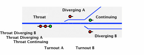
The turnout at the throat, is referred to as Turnout A and the other turnout is Turnout B. Six signal heads are possible--three at the throat, indicating the status of the Continuing track (top signal head), Diverging track A (middle signal head), and Diverging track B (bottom signal head), and one head at each of the three other tracks.
If requested, this tool will place signal icons on the panel at the six positions shown above and will set up control logic for each of the six specified signal heads. In some situations, a user may elect to only place one signal head at the throat, resulting in only four signal heads around the 3-way turnout. This tool will place the four specified heads, and will set up logic for the heads at the Diverging A, Diverging B, and Continuing tracks, but it cannot set up logic for the single head at the throat. Instructions on how to do that manually, with help from this tool are below.
Prior to selecting this tool, both turnouts must be on the panel, connected as shown by a single track segment, and required signal heads must be in the Signal Head Table. This tool places signal heads only when the main track of each turnout is vertical or horizontal (or mostly vertical or horizontal) on the panel, so design your panel accordingly. The control logic created by this tool only works correctly if each of the three track segments connected to the continuing and two diverging legs of the 3-way turnout is assigned to a different block, and those blocks are different from the block of the track segment connected to the throat of the 3-way turnout. The 3-way turnout (the two turnouts and their connecting short track segment) may be in a separate block or in the same block as the track segment connected to the throat.
When this item is selected, a dialog is shown for entry of the names (system or user) of the two turnouts, and the names (system or user) of six (or four) signal heads to be assigned to the 3-way turnout. You may enter both turnout names, or enter only one turnout and allow the program to find the other. If you enter only one turnout, make sure you put it in the correct position. To check that the second turnout has been found correctly, click the Get Saved button.
For each signal head, check boxes are available for selecting whether an icon is to be placed on the panel, and whether control logic is to be created for the signal head. Regardless of whether icons are placed or logic is created, Layout Editor will record that the entered signal heads are assigned to the specified turnouts. Assigning signal heads to turnouts is important to completely describe your layout in Layout Editor. Even if you elect to place your icons and set up your signal logic manually, you should use this tool to assign the signal heads to their 3-way turnout.
After a 3-way turnout is setup using this set up tool, Layout Editor keeps track of the fact that Turnout A and Turnout B are linked. So if you select Set Signals... in the popup menu of either turnout, you will return to this dialog with both turnouts filled in. If you should later desire to 'unlink' the two turnouts and add the missing signals, for each of the turnouts, select Set Signals at Turnout..., fill in the turnout name manually, enter signal heads, and click Done. After this is done for both turnouts, the turnouts will no longer be linked.
In the Turnout A Name and Turnout B Name field, enter the name (system or user) of one or two of the turnouts. If only one is entered, the tool will find the other when the Done or Get Saved buttons are clicked. If the tool cannot find the second turnout, or if the two entered turnouts are not on the panel or not connected as described above by a single track segment, an error message results. The turnout at the throat of the 3-way turnout must be entered as Turnout A, and the turnout farthest from the throat must be entered as Turnout B.
Signal Head names (either system or user) are entered in the next section. If signal heads at these turnouts have been entered previously, click Get Saved to retrieve the signal head names previously entered. The tool provides for entry of three signals at the throat and one each at the other three tracks. The throat signal heads and the Diverging A signal head are placed in Turnout A. The Diverging B and Continuing signal heads are placed in Turnout B. The Throat Continuing signal head (green in the above figure) reflects travel to the continuing track from the throat track. The other two throat signals reflect travel to their respective diverging tracks. If only one throat signal is entered, it should be entered in the Throat Continuing position.
If there was a signal head previously assigned to any position, and you enter a different signal head in the same place, the new signal head will replace the previous signal head, and the icon of the previous signal head (if there was one) will be deleted from the panel. Similarly, if you replace both previously assigned Throat Diverging signal heads with blank entries (no signal heads), the previous entries are deleted, and there will not be any signal heads at those positions. If a signal head is changed, you must redo any logic that involves it.
Check Add Signal Icon to Panel to request that an icon for a signal head be placed on the panel at the turnout position indicated. This tool can only place a signal icon on turnouts that are almost vertical or almost horizontal. If this is not so, a message is printed, and you should place the signal icon manually using the Layout Editor tool bar. Regardless, the signal head name is assigned to the specified turnout position. This assignment is important for setting up logic for other signals down the track. Assigning signal heads is also important in completely describing your layout in Layout Editor.
Check Set up Logic to request that the tool set up signal control logic for a signal head. For each of these signal heads, the tool creates a Simple Signal Logic for that head, and in addition where necessary, it creates a Logix that ensures that the turnouts are synchronized for the signal. The tool will attempt to setup the logic and automatically fill in entries from the information available. If the tool does not have enough information available to set up the logic, a message results, and you will have to return later after more blocks (with occupancy sensors) and/or signals have been assigned to turnouts and block boundaries on the panel. Note: This tool cannot currently set up logic for a single head at the throat of a 3-way turnout. See below for how to do so manually.
This tool will set up Simple Signal Logic in a standardized manner that should cover most cases. If the signals do not behave the way you want them to, feel free to edit the Simple Signal Logic manually to get the performance you want. To edit the simple signal logic for a signal head, in Edit Mode, summon the popup menu of the icon for the signal head whose logic is to be edited, and select Edit Logic.... Usually addition or removal of a sensor, or checking or unchecking an option, is all that is required. In more complicated cases, you may need to create a Logix to set the state of an internal sensor, that is then added to the Simple Signal Logic.
When setting up logic, this tool will follow track within a block until it finds a signal at the end of the block away from the turnout being signaled. If your layout contains sections that are signaled and sections that are not, to get this tool to set up logic correctly, you may have to create and assign a virtual signal (a signal that does not correspond to an actual signal on the layout) at the unsignaled end of the block that connects track that is signaled with track that is not signaled. (You do not need to add an icon for the virtual signal to your panel, but it must exist in your signal head table, and must be assigned to a turnout or block boundary using a Set Signals ... tool.) If a block ends with an end bumper, no virtual signal is required at the end bumper end.
If a block has an internal turnout (the turnout, and the track segments at its throat and continuing legs are within the block), the program will expect signals at that turnout even if it's not at the end of the block. However, at times the user may not want to signal a seldom used turnout within a block. When following track through a block, the program will skip over unsignaled internal turnouts if Skip Unsignaled Internal Turnouts is checked in the Layout Editor Tools menu. It will always, however, warn that it is doing so. Use this option with caution. There is no signal protecting against a skipped turnout being set incorrectly, so if an unsignaled internal turnout is not set correctly, derailed trains could result.
When setting up the Logix used in the control logic, the tool creates an internal sensor to communicate with the Simple Signal Logic. The Logix will appear in your Logix table, and the internal sensor will appear in your sensor table. The system names of the Logix and internal sensor will be, IX or IS followed by TTT_X_HHH, where TTT is the system name of the turnout where the signal head is located, X is either C or T depending on whether the signal head is located on the continuing (CLOSED) track or the diverging (THROWN) track, and HHH is the system name of the signal head. The purpose of this Logix is to ensure that the aspect of the signal head will be red if the turnout not in the Simple Signal Logic is switched against the track the signal head is signaling.
This tool sets up three-aspect signaling. When a signal head is showing status when moving to a diverging route, the tool will set up for limited speed (the least restrictive aspect is not green, but yellow), and the signal will show yellow when it otherwise would show green. You can change this with a simple edit (see below).
If you have a special situation at a signal, you may have to edit the information entered by this tool into the Simple Signal Logic. If you would like four-aspect signaling, you can easily manually edit the logic to achieve this. Similarly, by simple hand edits of the logic, you can add approach lighting. If you don't want yellow when moving to a diverging route, but prefer green, open the Simple Signal Logic for the head you want to change and uncheck Limited Speed. The Simple Signal Logic dialog can be accessed from the popup menu of each signal icon. If your special situation cannot be handled by Simple Signal Logic, you should refer to Logix to tailor the signal logic to your needs.
There are different ways to set up the logic for a single head at the throat of a 3-way turnout. The following procedure will work, and is fairly straightforward.
Define three virtual signal heads in the Signal Table, and enter them as the Throat - Continuing, Throat - Diverging A, and Throat - Diverging B heads, along with the real Diverging A, Continuing, and Diverging B signal heads. Virtual signal heads are signal heads that are not on the layout--only in the computer.
Check Set up Logic for each of the virtual signal heads, but do not check Add Signal Icon to Panel for any of these three virtual signal heads. Click Done. This will set up the logic for the three virtual signal heads.
Reopen the tool and clear the names of the three virtual signal heads. Place the real throat signal head in the Throat - Continuing position. Check Add Signal Icon to Panel, but do not check Set up Logic for this signal head. Click Done. The three virtual turnouts are no longer assigned to the 3-way turnout, but they are still in the computer and their logic will still function.
Set up a Logix to set the appearance of the single real throat signal head based on the appearances of the three virtual signal heads. Basically the real signal head should be set to the least restrictive of the appearances of the three virtual signal heads. This can be accomplished by a Logix with seven Conditionals with increasing numbers of simple state variables, set up as follows:
Where IHV1, IHV2, and IHV3 are the virtual signal heads, IH1 is the real head, and C1, C2, ... , C7 are Conditionals 1 through 7. Substitute the actual names of these items when you set up your Logix.
Please remember to save your panel after using this tool.