JMRI may be connected to the Digitrax DCS240 in any of a wide variety of ways. Since the DCS240 has a built-in USB interface, it is possible to simply plug a USB cable into the computer and the DCS240, and configure JMRI to suit this connection. It is also possible to use another LocoNet interface device, such as a LocoBuffer-USB, Digitrax PR3, or Digitrax PR4, to interface a computer to LocoNet, and connect that LocoNet to the DCS240. JMRI does not prefer any one connection method over any other method. Choose one which is suitable for your needs.
If a USB cable is used to connect the JMRI computer to the DCS240's USB connection, JMRI may be configured in one of two modes. If the computer will only be used for decoder programming, and JMRI will not need access to LocoNet features other than the DCS240 "programming track", then JMRI may be configured to use a "connection" where the DCS240 USB interface is placed into a mode where it acts as a standalone decoder programmer. In this mode, JMRI will access the DCS240 dedicated programming track connections. This mimics the "standalone programmer" configuration which the PR2 provides, and which the PR3 and PR4 can support.
Alternately, when JMRI will be used to access LocoNet resources which go beyond simply the DCS240 programming track, then JMRI should be configured to act as a general-purpose LocoNet interface. The JMRI "connection" should be configured so that the "command station" type specifies the type of command station which is being used.
If, instead of using the DCS240's integrated USB port, you plan to connect your computer to the DCS240 using a LocoNet adapter device, follow the instructions found here.
The table below summarizes these possibilities.
| Connection Type | Usage | Settings in JMRI Connection Profile< | Instructions | Available JMRI Capabilities | |
|---|---|---|---|---|---|
| System Connection | JMRI Command Station Type | ||||
| USB cable from computer to DCS240 USB connector | Decoder Programming | "DCS240 USB Interface" | "DCS240 Standalone Programmer" | Configuration help | Program decoder CVs on the dedicated programming track |
| Operate one loco on the dedicated programming track | |||||
| LocoNet Interface, Decoder Programming | "DCS240 USB Interface" | "DCS240 (Advanced Command Station)" | Configuration help | Program decoder CVs on the dedicated programming track and/or the main track | |
| Control one or more locos on the main track | |||||
| Control and monitor LocoNet-connected Switches, Sensors, and Transponding | |||||
| Configure some LocoNet devices | |||||
| Control or monitor the LocoNet Fast Clock | |||||
| Update firmware on some LocoNet devices | |||||
| etc. | |||||
| LocoNet Interface, Decoder Programming | Computer Connection to something other than the DCS240 USB connector | Something other than "DCS240 USB Interface" | "DCS240 (Advanced Command Station)" | Configuration help | Program decoder CVs on the dedicated programming track |
| Control one or more locos on the main track | |||||
| Control and monitor LocoNet-connected Switches, Sensors, and Transponding | |||||
| Configure some LocoNet devices | |||||
| Control or monitor the LocoNet Fast Clock | |||||
| Update firmware on some LocoNet devices | |||||
| etc. | |||||
Note that it is possible to use the DCS240 in a "booster" mode, and rely upon some other command station. If this configuration is used, the "command station" specified for the JMRI connection should match the device which is actually acting as the command station.
When setting up a JMRI "connection profile", which "command station" should you use when configuring JMRI? That depends on what you intend to do with JMRI.
If you wish JMRI to be able to control decoders via the DCS240 main track outputs, and access LocoNet devices, then configuring the connection for the "command station" type of "DCS240 USB Interface" mode is a good choice. In this mode, JMRI is able to control decoders connected via the main track outputs and access LocoNet devices. JMRI may also perform decoder programming via the dedicated programming track, but JMRI throttles will not be able to run decoders which are on the dedicated programming track.
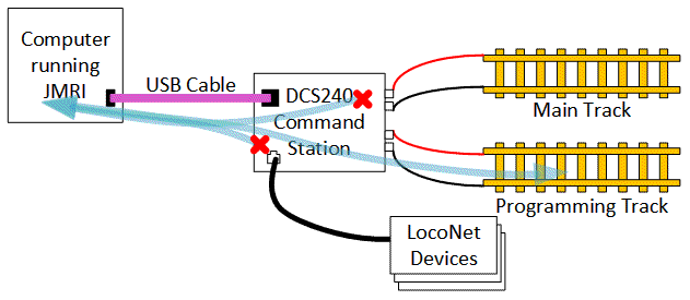
When the DCS240 USB interface is configured to act as a programmer, it acts upon the dedicated programming track via the "programming track" connections on the DCS240. When JMRI is properly configured, JMRI can use the DCS240 programming track to access decoder CVs when the decoder is connected to the programming track.
This JMRI configuration may also be used to download sound information into Digitrax sound decoders and, within its limited current capability, run one locomotive to test it. When used with Digitrax SFX decoders, "neutral mode" allows you to vary the speed without the motor moving the decoder, so you can hear how the locomotive sound reacts to varying speeds.
In this mode of operations, JMRI will not have access to LocoNet-based devices.
To use the DCS240 programming track, connect the DCS240 to its power supply and connect a dedicated piece of track which you'll use as the programming track to the DCS240 "programming track" terminals. Finally, connect a USB cable between the DCS240 and your computer.
To set up JMRI to use the DCS240 via the dedicated decoder programming track mode:
DCS240 USB
Interface as standalone programmer".The "connection" preferences should look similar to this image:

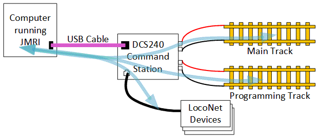
When acting as an interface, the DCS240 USB connection allows JMRI to interact with devices connected to LocoNet. This includes programming decoders on a programming track attached to a LocoNet command station. Where the LocoNet command station supports "programming on the main", JMRI is able to make use of that feature.
To use the DCS240 USB connection as a LocoNet interface, connect a LocoNet cable to a LocoNet connector on the DCS240. Connect an appropriate power supply to the DCS240, per the Digitrax instructions for the DCS240. The DCS240 USB interface will not be able to communicate with LocoNet unless the DCS240 is properly powered. Finally, connect an appropriate USB cable between the DCS240 USB connector and your computer.
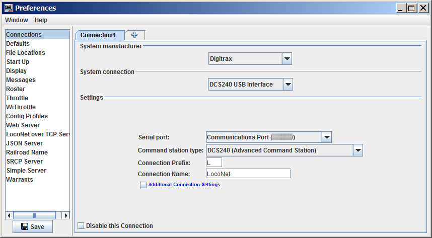
To set up a JMRI application to use the DCS240 as an interface to a LocoNet which includes a LocoNet command station:
DCS240
            (Advanced)
", but, if you have configured your DCS240 to act only as a
booster, you should select the command station option which matches the active command
station.The "connection" preferences should look similar to this image:
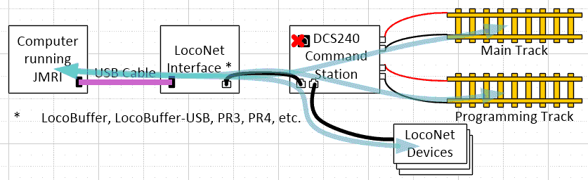
JMRI may connect to the LocoNet via a LocoNet interface other than the DCS24 USB connector. When connected in this fashion, these general instructions, or, where available, the JMRI documentation associated with the LocoNet interface which is being used.
You don't need to install a separate driver when using current versions of Mac OS X or Linux.
LocoNet® is a registered trademark of Digitrax, Inc.